Warning! The following article has been rated as MA and contains:
- Engineering language
- Mind violating knowledge
- HDD nudity
Joking apart, if you feel like you brain is going to shut down - take a break.
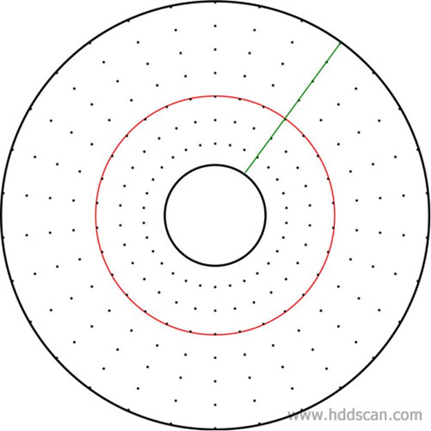
As you may know information is stored on platters and it's written by heads while platters are spinning. As any device which can store and retrieve information a hard drive needs to write data by special rules in order to read it back. HDD writes certain pieces on information in certain time frames, so to read data back HDD just calculates and synchronizes time, reads the pieces of information in certain time frames and decodes them. Let's imaging a generator that generates pulses in certain and equal periods of time, with each pulse a writing head writes piece of information in a certain format. If frequency of pulses in such a generator is constant then all time frames to write data on the drive would be the same and it will be very easy to write data on platters and read it back.
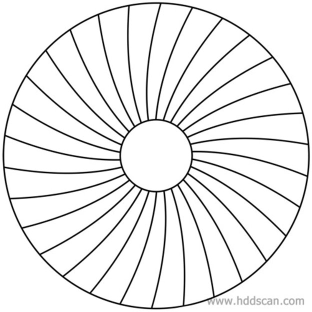
That's how it would look on a platter's surface.
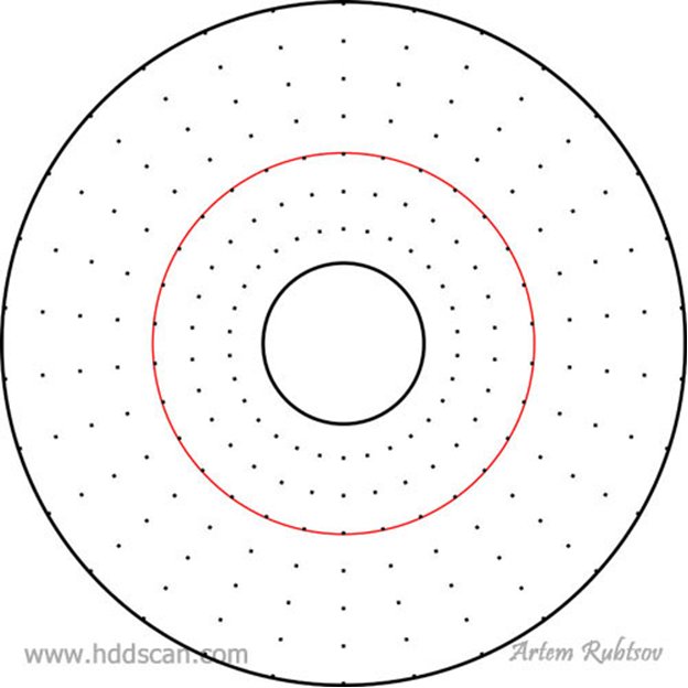
Black dots represent the beginning of writing with each pulse from the generator. The red circle represents path (one of them) which makes the writing head during data writing. Black circles represent inner and outer diameter of a platter (ID and OD).
As you can see if the frequency of writing is the same for the whole surface of the platter but the density of writing wouldn't be the same because the further the head goes toward OD the faster is linear speed of the platter in that point (even if the radial speed of the platter is constant). The data density that lies on the path of the head measured in Bits Per Inch or BPI. The path which makes head when flying above the surface is called a Track.
And here comes a problem
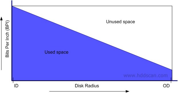
As you can see on this graph with single writing frequency the drive looses almost half of its platter's surface.
What would it be if we virtually divide platter on two rings. And the outer ring would have twice higher writing frequency than the inner ring.
Let's see how it helps:
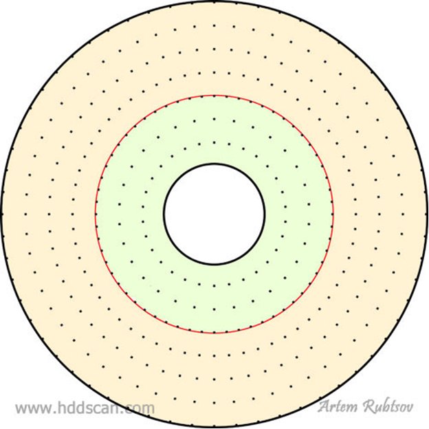
I highlighted our imaginary rings with different colors. Frequency in outer ring is twice higher than before and it helps to fit more data in it.
This is how it would look on a graph:
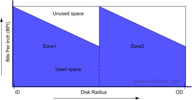
Imaginary rings with different writing frequencies called Zones. Zone0 represents outer ring and Zone1 represents inner ring. Zoning helps to fit more data on the platter's surface and makes platters usage more efficient.
Modern hard drives can have around 15-20 zones which makes platters usage very efficient.
But if you take real zone table from a drive and make a graph, you would see that this graph has a strange shape.
Something like this:
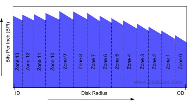
BPI is not even in different zones. Why would this happen? Actually it is a bunch of problems.
BPI drops a lot towards OD and there are two main reasons for this.
First thing: in order to keep BPI high drive has to increase writing frequency toward outer diameter. High frequency makes a read channel work harder when a drive reads data back. Beyond certain frequency the read channel just cannot distinguish data pieces and starts making too many errors. Such errors ratio is called Bits Error Rate or BER. BER is a one big nightmare for each and every HDD manufacturer.
To keep decent data consistency level manufacturers have to keep BER as much flat as possible regardless of the disk radius. And this leads to some cuts in frequencies toward OD.
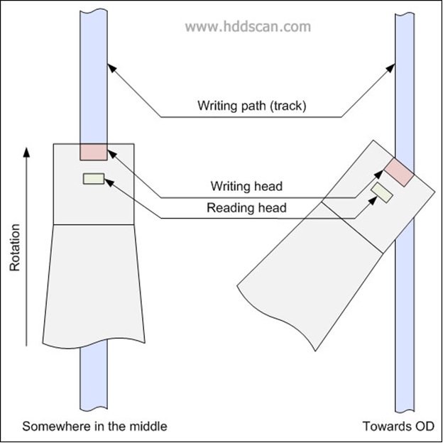
Second thing: tracks actually have different width. They are narrower toward OD and may narrow a little bit toward ID (it also causes small BPI drop toward ID). How would this happen, we know for sure that a writing head has a constant width?
Yes, the writing head width is constant but the angle of the writing head to a track tangent is variable and depends of the disk radius.
With less width a track delivers less magnetic power to the reading head and it makes data harder to distinguish and to make reading stable drive has to use lower writing frequencies on narrower tracks.
Let's talk about another density which called Tracks Per Inch or TPI. TPI measures how many tracks can be fitted into each inch of the disk radius. TPI is also non-linear and it also drops mostly toward OD. Why would this happen? Well, the thing is tracks are not perfectly circular, they may have fluctuating width, and they may be non-concentric which causes many problems.
Take a look on the next picture:
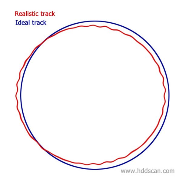
Tracks have such weird shape because of many factors. In general all these factors divided into two groups. The first group is called Repeatable Runout or RRO, examples of factors of this group are: platters shift and platters geometry irregularity. The second group is called Non-Repeatable Runout or NRRO and examples would be: vertical and horizontal platters vibrations/noise and air fluctuations. Because RRO and NRRO are higher on OD (radius is bigger) a drive's manufacturer would have to increase space between tracks toward OD which drops TPI. Also as we know tracks toward OD are narrower and this decreases TPI too.
Because realistic tracks are not really circular heads would have to move left and right a little bit to stay in the middle of a track when it's necessary. To do that drive generates Position Error Signal or PES that shows how far offtrack heads are in a specific moment of time.
To generate PES and move from track to track or seek any track or even tune up rotation speed a drive uses special coordinate system that's called Servo System. Modern drives use embedded servo system which means servo system information is spread among surfaces evenly. Servo System can be written only on a factory and cannot be fixed or re-written during drive's regular work and if Servo System gets severely damaged the drive is basically dead and it is not very cool but that's the way drives work.
There are three common ways to write servo on the platters:
- On a servowriter. The Servowriter or STW is a special device that is guided by lasers and has a special writing head on a special arm.
Pros of this method are: the STW writing head is usually narrower than writing heads on a drive and because of that a drive could fit more servo-tracks and the more servo-tracks the drive has the easier is to seek a track; With STW it is possible to make all servo-tracks with the same width (STW arm can rotate) and this makes BER for servo-tracks flat.
Cons of this method are: STW needs to write servo on all surfaces and this takes time and time is money; Obviously servo will be written on the platters before assembling and a drive would need firmware that can handle this situation. - With original heads stack guided by a special device (similar to STW). Maybe you saw some drives which have a hole at the side of HDA or/and at the bottom of HDA. These holes made especially to guide HSA during servo writing procedure. Modern preamps have a special mode, when a preamp would switch to such a mode it would turn on all writing heads on HSA and write incoming information on all surfaces at the same time. Guided by a special device HSA writes servo system on all surfaces at the same time.
Pros of this method are: It is faster and cheaper than the first method; Because drive writes servo after assembling - firmware can be less complex.
Cones of this method are: Drive still needs a special device to guide HSA and such device is very expensive; Drive with servo written after assembling has fewer abilities to resist geometric irregularities that may occur after assembling (firmware just cannot handle it). - With original heads guided by special pattern which is written on one of the surfaces. This method also called Self Servo Writing or SSW. The idea of this method is to write special pattern on one of surfaces of a drive with STW (before or after assembling) then assemble drive (if needed) and let the drive write servo by itself using the preamp in the simultaneous writing mode.
Pros of this method are: It is the cheapest method (writing only a pattern is much faster and does not take a lot of time of expensive STW); Because drive writes servo after assembling, firmware can be less complex.
Cone of this method is: Drive with servo written after assembling has fewer abilities to resist geometric irregularities which may occur after assembling.
Next picture will show you an example of servo system:
Black dots represent servo sectors. The red line represents servo-track and the green line represents servo sectors with the same number one all tracks, such a line is called a Wedge.
We have new word here - a Sector: sector is logically completed piece of data; sectors of similar type usually have the same logical length. Servo sectors are also called Servo Frames or Servo Marks.
As you can see servo sectors are written with one predetermined writing frequency and that's the main rule of the servo system. Using this knowledge drive can tune up rotating speed and also synchronize internal clocks with data frequencies in each zone. On modern drives frequency of servo sectors can be around 100 KHz. Usually there are 200-300 servo sectors per servo-track but as you also can see all the servo-tracks on a particular drive (actually all drives of a particular model) have exactly the same amount of servo sectors and in addition all servo sectors in a particular wedge have the same sector number. This knowledge helps a drive to calculate current heads position.
Real life wedges actually don't look like lines they look more like arcs. It's because when HSA or STW moves to create next servo-track, platters turn a little at the same time.
Take a look on the next picture:
This is how real life wedges would look on a platter (not that you could see them with a naked eye though).
What is inside of a servo sector? Let's see:
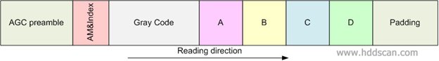
This is a usual servo sector. Format of the sector may vary in different models.
AGC preamble or just preamble it's a signal written with constant frequency and amplitude. It's used for automatic gain control - preparing drive to receive information from a servo sector.
AM&Index stands for Address Mark and Index signal. AM it's a special signal which basically marks the beginning of the Gray Code field. Index signal located only in servo sectors of the wedge number 0 (the other sectors have only AM), so such signal is generated only once per platter revolution. Using Index signal drive can easily tune up rotation speed or read the whole track into an internal buffer.
Gray Code field encodes a servo-track number. The servo-track number is encoded with redundancy and with Gray code (special noise immune code). Drive needs such encoding for very fast and consistent reading of a servo-track number, even in some fast seek modes. All servo sectors on a servo-track have the same servo-track number encoded.
Signals A,B,C,D also known as position signals - special signals written with constant frequency and amplitude but some of them are written offtrack (see a picture below). Drive uses A-B-C-D to generate PES.
Padding marks the end of the servo sector - it's a signal with constant frequency and amplitude.
Next picture will explain how drive uses A-B-C-D for positioning to a center of a servo track:
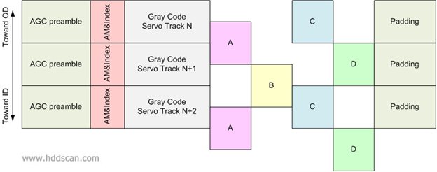
This picture shows three servo sectors from the same wedge.
Servo tracks on this picture are shown without space in between them but all tracks have some space between each other.
As you can see some of the A-B-C-D signals are written offtrack and to make that happen STW or a drive writes each servo track in several passes.
For example, drive would like to stay in the middle of the Servo Track N+1: Signal A should be read with half of the amplitude, considering increasing amplitude when the head moves to the left off the track (to the top of the picture). Signal B should be read with half amplitude considering increasing amplitude when head moves to the right off the track (to the bottom of the picture). Signal C should have amplitude close to nothing and Signal D should have full amplitude. That's how the drive knows current heads position.
Now let's talk about data. How drive stores it? The user data is stored in data sectors and data sectors are grouped to data tracks.
Next picture shows how a data sector would look on a modern HDD:
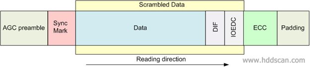
AGC preamble is used for Automatic Gain Control. Sync Mark is a special field with constant digital info in it. Because it's a predetermined field and it's the same in all data sectors drive can use this to tune up PRML decoder (Modern hard drives use PRML encoding/decoding to store data on platters) also drive knows that data goes right after sync mark and drive uses it for data decoding synchronization. User data may be followed by several fields, in this sector data followed by DIF - Data Integrity Field, IOEDC - Input/Output Error Detection Code and ECC - Error Correction Code. Data sector may be closed by a padding.
ECC detects and corrects on the fly (if possible) errors that may occur durung data sector read from platter's surface.
IOEDC field checks data when it goes from drive's formatter (Read/Write system) then through de-scrambler until it outs drive's cache memory and goes to drive's interface frame buffer.
DIF field checks data when it goes from the frame buffer then through interface cable and finally to the host (DIF check is available only on certain interfaces, like SAS or FC). And for even more data protection, the drive generates CRC when data goes out of the frame buffer and through the cable. All modern interfaces support the CRC check feature. This CRC is not written into a data sector but generated on the fly.
As you see one can never be too paranoid to protect data.
When a host computer sends data to a drive to write, the actual data will not be written as is. It will be scrambled. Usually that would mean data will go through randomizer and RLL encoder, why? Let's imaging that a drive would like to write one sector with only zeroes inside and let's imaging the drive writes it as is and then tries to read it back. And here is the problem - drive may lose synchronization when reading a signal that is not changing for a long period of time, the drive will become blind and will fail to read data. To fix this problem drive uses an RLL encoder. The RLL encoder mixes up data with redundant information and makes sure that a bunch of bits fatal for synchronization would never occur. Randomizer before RLL encoding makes drive's life easier and the drive can use less complex RLL encoders.
The ECC field is a vital necessity for HDD because data written with high frequency (up to GHz) almost on the border of drive's limits. When drive reads data back it is very possible that data in the sector would have minor errors and ECC makes it invisible correcting it on the fly. Such technology helps to fit as much data as possible. But heads for a drive cannot be made exactly similar; each head has unique electric, magnetic and geometric characteristics. And here comes another problem: let's say we have a drive with 4 heads inside and Head 0 can fit 1000 sector on a particular data track, Head 1 however can fit only 950 sectors on a data track with the same number but located on a surface for Head1; and it is very possible that Head 2 can fit only 900 sectors but Head 3 is a champion and can fit 1050 sectors. In order to keep writing frequency similar in a particular zone for all heads we would have to select Sector Per Track or SPT as 900 sectors for all heads and that means we don't use all capabilities of a hard drive. Such schema were used in older HDDs but moderns drives can actually select unique writing frequency for each head in each zone and this schema called Variable Bits Per Inch or VBPI. Zone tables for VBPI drives store SPT for each head in each zone.
Same thing about data tracks some heads can write with larger TPI but some won't and modern hard drives may use different TPI for different heads in different zones, such feature is called Variable Tracks Per Inch or VTPI. Having VTPI on a drive means that empty space between data tracks varies from head to head and zone to zone and that leads to a logical conclusion - centers of servo tracks and data tracks do not match.
Take a look on the following picture:
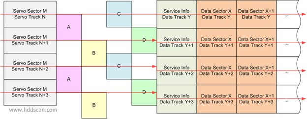
Servo and data tracks on this picture include space between tracks.
Because space between data tracks likely will be wider than space between servo tracks, the data tracks look thicker. As we know drive can only position on a servo track because only servo sectors have A-B-C-D positioning fields but the goal is to read and write data, how drive knows where a data track is? It is simple - drive calculates it. VCM controller has ability to step to a side from the center of a track by adding certain amount of current into actuator circuit. Such step is called DAC (basically it's digital to analog conversion). Each servo track can be virtually divided longitudinal on particular number of DACs, like 64, 128 or 256 DACs. When drive needs to read a data sector, first drive calculates closest servo track to a data track thus jump to the center of data track from the servo track would be less or equal half of the servo track width. Then drive seeks desired servo track and positions to its center and after that drive shifts heads position on the calculated number of DACs to get positioned on the center of the data track. Red lines on the picture represent path heads making to get on data tracks.
HDD is a precise device and all inside works under a watch of clocks. Drive reads every servo sector on a servo track even when drive needs to read or write data. Drive knows when next wedge will appear because drive calculates time. Reading each servo sector helps when drive needs to correct heads position. To do such a complex job drive separates servo sectors reading and data sectors reading. Servo sectors read by Servo Processor and special signal - Servo Gate tells Servo Processor when to read next servo sector the same Servo Gate signal pauses the Formatter. Formatter responsible for reading and writing data sectors. Formatter can generate two signals Read Gate - for reading data sectors and Write Gate - to write them. Gate signals are hardware related and this helps to start and stop R/W channel and preamp's work when necessary. For example: until Write Gate signal comes drive will not be able to write, physically, because preamp will not allow heads to write. As you may notice because Servo Gate pauses the Formatter servo sectors can never be re-written in regular mode, if drive works properly.
Because reading each servo sector is such a critical job data sectors reading considered less important task and a data sector can be split into pieces by wedges. Now you know how drive calculates position for the center of data track and if data track for some reason will not be in calculated position - data will be unreadable that's one of the reasons why hard drives are sensitive to vibrations. If drive vibrates, too much RRO and NRRO can cause offtrack for the data track positioning and it's especially dangerous when drive writes.
Another problem what drive has to fight is that reading and writing cannot be done at the same time for the same track even if there is full duplex hardware support, it is still impossible.
And the reason of that problem is described on the next picture:
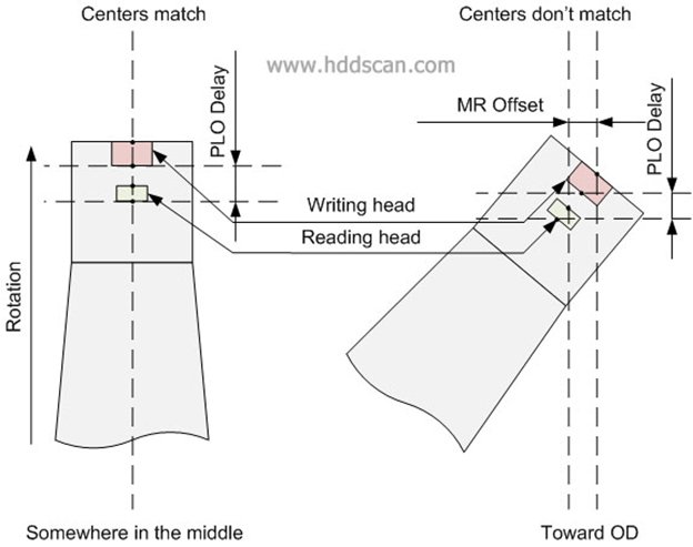
Writing head is magnetically shielded from reading head and this causes a gap between heads.
When heads flying above track in the middle of a platter, centers of reading and writing head will be above the center of the same track and drive can read and write on the same track without moving heads. But if, for example, heads move toward OD, centers of reading and writing heads will not be above the same track, one of the heads will be far offtrack (sometimes several tracks aside). Such a difference between centers of reading and writing heads is called MR Offset. MR Offset is not a constant it varies from track to track; it also can be negative (for ID) and positive (for OD). MR Offset depends on a track location and track width. Another parameter is called PLO Delay or Read-Write Delay. It shows difference between Read Gate and Write Gate appearances. On different tracks PLO Delay will be different for Write Gate. As we know each head has unique parameters and MR Offset and PLO Delay also will be unique for each head. Drive stores averaged MR Offset and PLO Delay for each head at least for each zone in special tables called Adaptive tables or just Adaptives (adaptives also include some other critical parameters). Adaptives may be stored of the platters in special area called System Area or SA. System Area contains part of drive's firmware. And here is a dilemma: drive basically cannot read and write w/o adaptives but to get adaptives drive supposed to read SA first, what to do? Here is the solution: SA is formatted with predetermined TPI and BPI in a known place of platters and that allows drive to read SA w/o adaptives. Most of modern drives write SA in the middle of platters, so the drive would have ability to write SA w/o adaptives. But for data area drive has to calculate DACs for reading and writing procedures separately, with MR Offset included. If adaptives are lost the a drive may become totally helpless and data may be lost forever. Some drives put part of adaptives into flash and that makes PCB unique for each drive.
At the end I would like to tell you about serpentine reading/writing. Imaging that you have a drive and that drive has 4 heads and you want this drive to do linear reading or writing. Apparently drive has to use all the heads and it's understandable that you would like to get maximum speed from this drive. To minimize heads movements, when a drive switches from head to head, it would be logical if the drive would read all tracks from one head and then move to another head etc. But it's going to create a problem - the very first head most likely would have more loading than the other heads.
To minimize heads movements and equalize each head usage, different drives use different clever schemas of reading/writing. Take a look on the next picture.
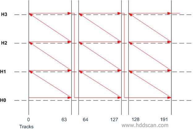
The red line represents path which would make HSA during linear reading or writing. As you can see it's zigzag or serpentine movements. The number of tracks in a serpentine could be different for different drives and on modern drives it also could be unique for each head on each drive (because each head can have different TPI and variable serpentine would help to decrease movements of HSA). Serpentine schemas vary from model to model and it also can be backward reading serpentine for odd heads but the idea is the same for any drive.
I hope you enjoyed this article. If you have any questions related to tracks, zones or positioning, please ask them by e-mail: support@hddscan.com
Please Note:
This article has been written exclusively for hddscan.com
If you would like to publish or reproduce any part of this article on other Internet recourses you would have to get an agreement signed by the author of this article.